Meshes
A triangle mesh is how a slicer, a scanner or a download hands over a shape. This tutorial makes meshes, colours them, saves and reads them, cuts them back into regions and takes them into booleans.
A mesh from vertices and faces
polymesh.Mesh takes the corners as an N-by-3 matrix and the triangles as rows of three indices into it. A tetrahedron needs four of each. The mesh is closed, every edge shared by two triangles, so it encloses a volume.
V = [0, 0, 0; 30, 0, 0; 15, 26, 0; 15, 8.7, 24.5];
F = [1, 3, 2; 1, 2, 4; 2, 3, 4; 3, 1, 4];
M = polymesh.Mesh (V, F)
isclosed (M)
volume (M)
show (M);
M =
polymesh.Mesh: 4 vertices, 4 triangles
ans = 1
ans = 3185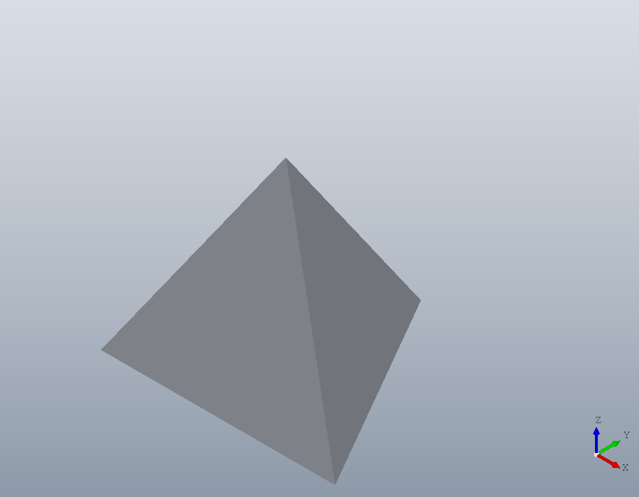
A mesh from a surface Octave computes
isosurface returns a struct with the fields vertices and faces, the form patch takes, and the constructor takes it as it is. Two blobs joined at a waist:
[x, y, z] = meshgrid (linspace (-20, 20, 41));
v = 1 ./ ((x - 8) .^ 2 + y .^ 2 + z .^ 2 + 1) ...
    + 1 ./ ((x + 8) .^ 2 + y .^ 2 + z .^ 2 + 1);
B = polymesh.Mesh (isosurface (x, y, z, v, 0.025))
B =
polymesh.Mesh: 1750 vertices, 3496 trianglesColours
A mesh carries a colour for each vertex, VertexColour, or for each triangle, FaceColour, as rows of red, green and blue from 0 to 1. Here each vertex is coloured by its height, blue at the bottom and red at the top. In the viewer the key C turns between the colours a mesh has.
h = B.Vertices(:,3);
t = (h - min (h)) / (max (h) - min (h));
B.VertexColour = [t, 0.3 * ones(size (t)), 1 - t];
show (B);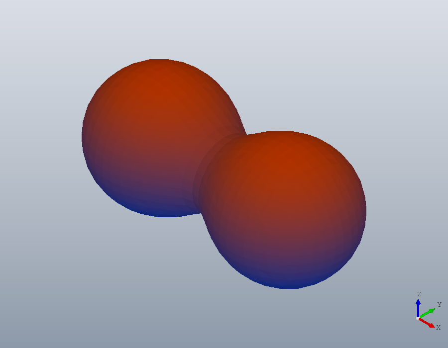
Moving, turning, mirroring and scaling return a new mesh, as every method of the package does. bbox gives the extent, and its second output the size along each axis.
B2 = scale (rotate (B, 90, [0, 0, 1]), 2);
[~, L] = bbox (B2)
L =
27.034 58.271 27.034Files
A part from a CAD program reaches a slicer as a mesh. tessellate makes one of a solid, here a plate with a bore, and write saves it in the format its extension names: STL, OBJ, PLY or 3MF. polymesh.read reads all four back, and every one keeps the mesh whole.
S = solid.extrude (geom.Region ([0, 0; 60, 0; 60, 30; 0, 30], ...
                                {[22, 15, 1; 38, 15, 1]}), 8);
T = tessellate (S, 0.05);
files = {'plate.stl', 'plate.obj', 'plate.ply', 'plate.3mf'};
for k = 1:numel (files)
  write (T, files{k});
  R = polymesh.read (files{k});
  printf ("%-10s %d vertices, %d triangles\n", files{k}, ...
          numvertices (R), numfaces (R));
endfor
plate.stl 88 vertices, 176 triangles
plate.obj 88 vertices, 176 triangles
plate.ply 88 vertices, 176 triangles
plate.3mf 88 vertices, 176 trianglesSTL repeats every corner for each triangle that uses it; polymesh.read welds them back into one vertex, so the counts agree.
Cutting a mesh
A part that arrives as an STL file has no model behind it, only its triangles. This one is the bracket of the coordinate systems tutorial, built here and written as an STL, then read back as a mesh with nothing exact left in it.
bracket = union (solid.box (90, 40, 8), ...
                 translate (solid.wedge (60, 40, 30, 10), [0, 0, 8]));
U = geom.UCS ([0.5144957554, 0, 0.8574929257], [60, 0, 8], [60, 1, 8]);
slot = geom.Region ([16, 15, 1; 24, 15, 0; 24, 40, 1; 16, 40, 0]);
slot.UCS = U;
bracket = pocket (bracket, slot, Inf);
bracket = fillet (bracket, edges (bracket, 'Direction', [0, 0, 1], ...
                                  'Within', [85, -1, -1, 91, 1, 9]), 5);
bracket = hole (bracket, [75, 12, 8; 75, 28, 8], 6, Inf);
write (bracket, 'bracket.stl');
M = polymesh.read ('bracket.stl')
M =
polymesh.Mesh: 406 vertices, 820 trianglesTo remake its plate, the mesh is cut through the plate, half way up. pickucs with 'points' picks the plane from three points, which need not lie on one face: here the middles of three upright edges of the plate, all 4 above its base, where the rounded corner meets the end of the plate, at the far corner of that end, and where the rounded corner meets the front. On a mesh a click snaps to a corner of the triangle under it, or to the middle of one of its sides when it lands near, so each of these takes the middle of its edge.
V = show (M);
[U, CODE] = pickucs (V, 'points')
U =
geom.UCS: origin [90, 5, 4], x axis [0, 1, 0], normal [0, 0, 1]
CODE = geom.UCS ([0, 0, 1], [90, 5, 4], [90, 6, 4])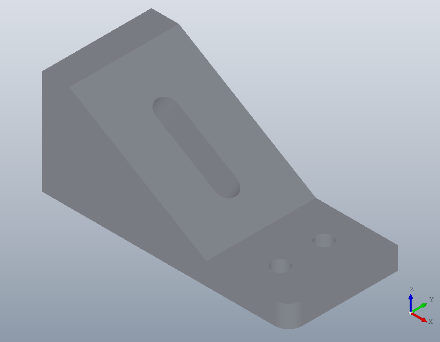
CODE goes in the script in place of the pick, and section cuts the mesh with the plane, as it cuts a solid, returning the cut as regions. The cut of a mesh is made of its facets, so the rounded corner and the holes come back as polygons of straight segments.
U = geom.UCS ([0, 0, 1], [90, 5, 4], [90, 6, 4]);
C = section (M, U);
C{1}
ans =
geom.Region: an outline of 22 segments, 3 holesfit turns the segments back into lines and arcs where they follow them within a tolerance, a thousandth of the region's size by default. The outline is four straight sides and the rounded corner, one arc, and each bolt hole is two arcs, a circle. The slot runs through the plate at a slant, so its ends are parts of ellipses, which arcs can only follow within the tolerance: each end comes back as two arcs and a short line.
R = fit (C{1});
R.Outline
R.Holes{1}
R.Holes{2}
ans =
geom.Path: closed, 5 segments, 1 arc, 0 splines
ans =
geom.Path: closed, 2 segments, 2 arcs, 0 splines
ans =
geom.Path: closed, 8 segments, 4 arcs, 0 splinesThe region is the plate as it was drawn, and extruded half its thickness each way from the plane of the cut, it is an exact solid again. Only the slot, which runs through the part at a slant, now runs straight down, as its cut half way up has it.
plate = solid.extrude (R, [4, 4]);
[~, L] = bbox (plate)
show (plate);
L =
90 40 8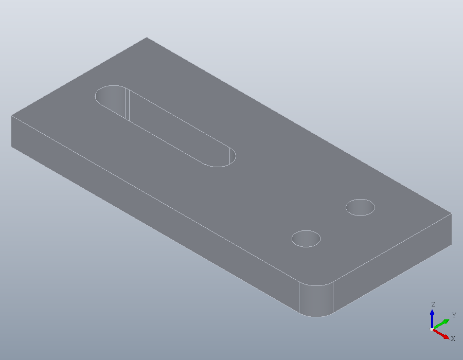
A mesh with a gap
A mesh from a scan or a careless export may have holes in its surface. Taking away one triangle of the bore of the plate saved under Files makes one here. The cut through the gap no longer closes: section returns what it can make into regions, the plate without its bore, and the rest in a second output, as chains of points.
c = (T.Vertices(T.Faces(:,1),:) + T.Vertices(T.Faces(:,2),:) ...
     + T.Vertices(T.Faces(:,3),:)) / 3;
[~, k] = min (sum ((c - [30, 7, 4]) .^ 2, 2));
G = polymesh.Mesh (T.Vertices, T.Faces([1:k-1, k+1:end],:));
isclosed (G)
[C, OPEN] = section (G, geom.UCS ([0, 0, 1], [0, 0, 4]));
C{1}
numel (OPEN)
gap = norm (OPEN{1}(1,:) - OPEN{1}(end,:))
ans = 0
ans =
geom.Region: an outline of 4 segments, 0 holes
ans = 1
gap = 0.6277The gap is one facet wide. A 'Tolerance' just larger than it joins the ends and closes the bore again, and fit makes it round. Keep it small: one much larger than the gap merges points of the cut and coarsens it.
C = section (G, geom.UCS ([0, 0, 1], [0, 0, 4]), 'Tolerance', 0.7);
R = fit (C{1});
R.Holes{1}
ans =
geom.Path: closed, 2 segments, 2 arcs, 0 splinesMeshes in booleans
solid.polyhedron makes a solid of a closed mesh, so a mesh takes part in booleans like any other shape. A hole through one of the blobs:
P = solid.polyhedron (B);
H = subtract (P, solid.cylinder (3, 50, geom.UCS ([0, 1, 0], [8, -25, 0])));
show (H);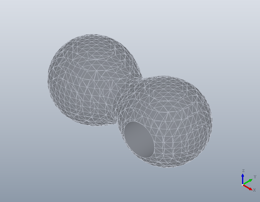
How fine a tessellation is
The second argument of tessellate is how far, in millimetres, a triangle may stray from the true surface, 0.01 by default. No triangle spans more than 20 degrees of a curve either, which is why the two coarser tolerances give the same mesh of this plate.
for tol = [1, 0.1, 0.01, 0.001]
  printf ("%6.3f mm: %d triangles\n", tol, numfaces (tessellate (S, tol)));
endfor
1.000 mm: 160 triangles
0.100 mm: 160 triangles
0.010 mm: 376 triangles
0.001 mm: 1144 triangles