Categories &
Functions List
Function Reference: draw.linetype
drafting: NAMES = draw.linetype ()
drafting: PATTERN = draw.linetype (NAME)
drafting: [PATTERN, DESCR] = draw.linetype (NAME)
Dash patterns of the standard line types.
NAMES = draw.linetype () returns the names of every line type
the package defines, as a cell array of character vectors.
PATTERN = draw.linetype (NAME) returns the dash pattern of
one of them, as a row vector in millimetres. A positive element is a drawn
dash, a negative element a gap, and a zero a dot. 'CONTINUOUS' has an
empty pattern. The patterns are the metric ones CAD programs define, so a
hidden line is dashes of 6.35 with gaps of 3.175.
[PATTERN, DESCR] = draw.linetype (NAME) also returns
a human-readable description, which is what a DXF line-type table carries.
The set
'CONTINUOUS' | unbroken; visible edges |
'HIDDEN' | short dashes; edges concealed by the body |
'CENTER' | long-short-long; axes of symmetry, pitch circles |
'PHANTOM' | long-short-short; alternate positions |
'DASHED' | even dashes |
'DASHDOT' | dash and dot |
'DOT' | dots only |
The names follow the CAD convention rather than the ISO 128 line-type numbering, because they are what a DXF file and every CAD program expect to see.
One rule for the lengths, everywhere
The lengths are model dimensions, multiplied by a line-type scale
factor. That is the rule CAD uses — its LTSCALE — and it is the
rule every backend here follows, because a DXF line-type table defines the
lengths that way and the file backend has no choice.
Each backend defaults the factor to whatever makes its own medium sensible, and each lets a caller say otherwise:
| Backend | Default | |
|---|---|---|
plot | 1 | on screen at 1:1 the pattern is already the right size |
tikz | the drawing scale | cancels the reduction, so dashes reach the page at nominal size |
write | 1 | written into the file as
$LTSCALE, so the recipient’s CAD does not supply its own |
A centre line therefore reads as a centre line whether its view is drawn at 1:1 or at 1:50, without the package having to hold two contradictory ideas of what a dash length means.
Line types are names, not an enumeration
Nothing in this package restricts an entity to these seven. A name it does not recognise is carried through to the output unchanged, so a drawing may use a line type defined by the receiving CAD installation or by a company standard. Only the ones listed here can have their pattern written into a DXF line-type table; an unknown name is emitted by name alone, which is exactly how a CAD file refers to a line type its recipient already has.
See also: draw.Drawing, draw.colour, draw.Drawing.write
Source Code: draw.linetype
The seven standard line types, by name, with the dash pattern each carries. A positive element draws, a negative one skips, a zero is a dot.
draw.linetype ()
ans =
{
  [1,1] = CONTINUOUS
  [1,2] = HIDDEN
  [1,3] = CENTER
  [1,4] = PHANTOM
  [1,5] = DASHED
  [1,6] = DASHDOT
  [1,7] = DOT
}
draw.linetype ('CENTER')
ans =

   31.7500   -6.3500    6.3500   -6.3500
[pat, descr] = draw.linetype ('PHANTOM')
pat =

   31.7500   -6.3500    6.3500   -6.3500    6.3500   -6.3500

descr = Phantom ____ _ _ ____
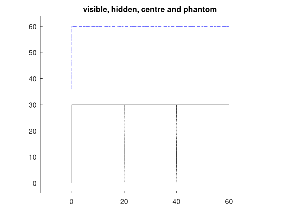
What each one is for, drawn. A centre line marks an axis, a hidden line an edge concealed by the body, a phantom line an alternate position.
 D = draw.Drawing ();
 D = D.polyline (geom.Polyline ([0, 0; 60, 0; 60, 30; 0, 30], ...
                                'Closed', true));
 D.Linetype = 'HIDDEN';
 D = D.line ([20, 0], [20, 30]).line ([40, 0], [40, 30]);
 D.Linetype = 'CENTER';
 D.Colour = 'red';
 D = D.line ([-6, 15], [66, 15]);
 D.Linetype = 'PHANTOM';
 D.Colour = 'blue';
 D = D.polyline (geom.Polyline ([0, 36; 60, 36; 60, 60; 0, 60], ...
                                'Closed', true));
 plot (D);
 title ('visible, hidden, centre and phantom');